When assessing the heat costs (required thermal power) for heating a liquid (gas) when it flows in a pipeline that has an external heat source (for example, an electric heater), appropriate methods for calculating various heat exchangers are used. When calculating heat exchangers, the power of the source, the design characteristics of the source, pipeline, heat transfer substrates, electrical insulation, thermal insulation, their thermal characteristics, liquid (gas) characteristics, loss values, etc.
However, to answer the first and main question ("What power is needed to heat the coolant at a flow rate of, for example, 0.2 kg/s per twenty degrees?") is not required deep knowledge of heat exchange processes. To calculate the thermal power (corresponding to the electrical power without taking into account small heat losses), it is enough to know the heat capacity coefficient of the liquid (gas) and apply the formula below. Just first you need to evaluate what kind of liquid flow (for example, water) you need. If necessary, you can convert mass flow to volume flow, knowing the density of the liquid (gas).
The value of thermal power [the amount of heat (thermal energy) per second], which must be transferred to the flow of liquid or gas to increase its temperature to the required value, is calculated by the formula
Q = G · Cp· dT, [1]
where
Cp – fluid specific heat, J/(kg·oC);
G – the fluid rate of flux, kg/s;
dT – change in the temperature of the liquid (gas) in the pipeline section, oC, K
For conversion between force systems it is used the following dependence: 1 cal = 4,1868 J.
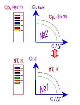
The scheme of the system of nomograms for the graphic-analytical calculation of the parameters of heating the liquid in the pipeline is shown in Figure 1.
After applet start an auxiliary window will have the following appearance (drawing 2).
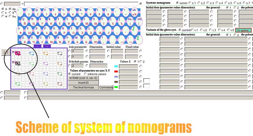
In an auxiliary window the circuit design of disposing of nomographs is already shown, but she demands recurring feeding into, therefore on each small square which is marking out a nomograph "is clicked" by the right key of the mouse and the left key "clicked"on that place where there should be a colour flag indicator (a place of disposing of meaning of parametre Z of a nomograph). It is possible choose any other location of variable parametre Z. After recurring appointment of the circuit design of nomographs "is clicked" by the left key of the mouse on sign "[-]", had in left overhead to the angle of the circuit design of nomographs. It will change the aspect on "[+]". It means, that the circuit design of nomographs is fixed. .
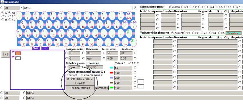
After attaching of the circuit design of nomographs, "is in succession clicked" on everyone sign, marking out a nomograph, and it is pushed three buttons "In the working memory" ("В ОЗУ"), "Substitution ID" ("Подстановка ИД"), "the Total formula" ("Итоговая формула") for entering of all parametres of a nomograph into an on-line storage and design formula formation.
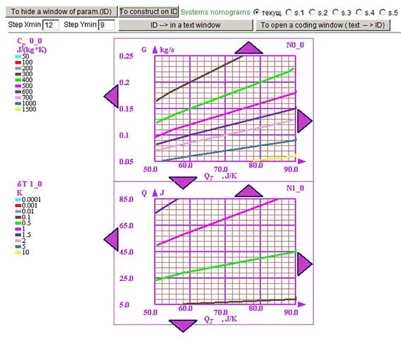
We transfer to the basic window and we induct meanings of steps on axes "X" and "Y". We push the button "to Build on ID" ("Построить по ИД").
More detailed instruction on operation with an applet.
Applets on this site "nomogramka.info" can be used as calculators formulas.
The topic of this section is to determine the thermal power required to heat the fluid flow in the pipeline.
graphic-analytical systems
Copyright © 2005-2022 All rights reserved